Master High-Speed I/O Expansion with EPM1270T144C5N

Learning how to implement high speed I/O expansion and bus bridge function with EPM1270T144C5N can simplify what might seem like a challenging task. The EPM1270T144C5N is a programmable device designed to handle complex I/O configurations with ease. Its advanced features enable faster data transfer between devices, making it an excellent choice for improving system performance. By understanding how to implement high speed I/O expansion and bus bridge function with EPM1270T144C5N, you can create systems that are both faster and more reliable.
Key Takeaways
The EPM1270T144C5N is a strong tool for fast I/O tasks. It has 116 I/O pins and works in 6.2 nanoseconds.
Setting up hardware and pins correctly is very important. Always check wires and voltage to avoid problems.
Use Intel Quartus Prime software to program and test designs. Simulations can find timing problems before using the hardware.
Keep signals clean by using shielded wires and proper grounding. This lowers noise and makes the system work better.
Design systems that can grow easily for future needs. This keeps them fast and useful as requirements change.
Understanding the EPM1270T144C5N
Key Features for High-Speed I/O Expansion
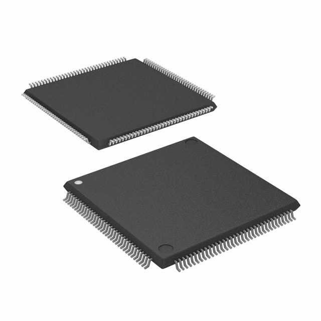
The EPM1270T144C5N is a powerful device that simplifies I/O setups. It works well for fast data transfer and smooth connections. This device has 116 input/output pins, which helps expand system capacity. Its delay time is only 6.2 nanoseconds, making it very quick for high-speed tasks.
This device is part of Intel's MAX® II series, known for being programmable. You can adjust it to fit specific needs. It works with voltages between 2.5V and 3.3V, making it good for low-power uses. Its small 144-TQFP package fits easily into tight spaces.
Here’s a simple look at its specs:
Product Attribute | Attribute Value |
|---|---|
Manufacturer | Intel |
Voltage Supply - Internal | 2.5V, 3.3V |
Supplier Device Package | 144-TQFP (20x20) |
Series | MAX® II |
Programmable Type | In System Programmable |
Package / Case | 144-LQFP |
Operating Temperature | 0°C ~ 85°C (TJ) |
Number of Macrocells | 980 |
Number of Logic Elements/Blocks | 1270 |
Number of I/O | 116 |
Delay Time tpd(1) Max | 6.2 ns |
These features make it a great choice for fast I/O expansion.
Why It Excels in Bus Bridge Functions
The EPM1270T144C5N is great for bus bridge tasks because it is programmable and fast. It connects different communication systems, helping data move smoothly. Its 1270 logic elements allow it to handle complex tasks, and 980 macrocells boost its power.
Its low delay time helps data move quickly, avoiding slowdowns. It works well in temperatures from 0°C to 85°C, so it’s reliable in many places. Its small size and many I/O pins make it perfect for systems needing good connections and growth.
By using its features, you can build systems that are fast and ready for future upgrades.
How to Implement High-Speed I/O Expansion and Bus Bridge Function with EPM1270T144C5N
Preparing the Hardware and Pin Configuration
First, set up the hardware for the EPM1270T144C5N. This device has many I/O pins, making it great for fast data tasks. Start by finding the pins you need for your project. The EPM1270T144C5N includes 116 I/O pins, which help connect more devices. Check the datasheet to plan the pin layout and match it with communication systems.
When adding external devices, keep signals clear. Use shielded wires and good grounding to lower noise. Since the EPM1270T144C5N is programmable, you can adjust it for different uses. Always check the voltage (2.5V or 3.3V) to protect the device from damage.
Setting Up the Development Environment
To prepare the development tools, install Intel Quartus Prime software. This tool lets you program the EPM1270T144C5N and create custom designs for I/O expansion. Set the software to match the device’s specs, like delay time.
Community tips show that delay times can change in different setups. These tips help you fix timing issues and improve performance. For instance, the EPM1270T144C5N has a delay time of 6.2 nanoseconds, which supports fast data movement. Use simulators to check timing before using your design.
Designing and Implementing I/O Expansion Logic
To design I/O expansion, create a plan for connecting devices. Choose the communication systems your project needs. The EPM1270T144C5N works well with many protocols, making it flexible for different tasks.
Use its features to build bus bridge functions. Its 1270 logic elements let you create advanced connections between devices. Focus on making the design fast and efficient. Test each part of the design to ensure it works and can grow.
Tip: Break your design into smaller parts for easier fixes and updates.
Testing and Debugging the Setup
Testing ensures the EPM1270T144C5N works as planned. First, check all hardware connections. Match each pin to your design plan. Make sure connections are tight and meet voltage needs. Loose wires or wrong setups can cause problems.
Next, use Intel Quartus Prime software to test your design. Simulations help find issues before using real hardware. Focus on timing analysis. The EPM1270T144C5N is fast, but bad timing can slow it down. Fix any timing problems you find.
After testing, program the device with your design. Load it onto the EPM1270T144C5N and watch how it works. Use test signals to check the I/O setup. Look at the output to see if it’s correct. If something is wrong, adjust your design.
Debugging means finding and fixing errors. Use a logic analyzer to follow signal paths. This tool shows where problems happen. For example, if a signal stops, check the related logic part. The EPM1270T144C5N lets you quickly make changes.
Finally, test the system with real data. Check if it handles signals well and stays fast. This step proves your setup is reliable for high-speed tasks.
Tip: Write down test results. This helps track progress and spot repeated problems.
By testing and debugging, you can learn to use the EPM1270T144C5N for fast I/O expansion and bus bridge tasks. These steps are key to building a strong and efficient system.
Best Practices for High-Speed I/O Expansion
Keeping Signals Clear and Reducing Delays
Clear signals are key for fast I/O expansion. Signals must stay clean and undistorted when moving through the system. Problems like noise or jitter can cause errors and slow things down. To prevent this, reduce electromagnetic interference (EMI). High data speeds can increase EMI, which messes up signals. Use shielded wires and good grounding to lower this risk.
Another issue is ground plane resonance. This can make your system act unpredictably and hurt signal quality. To fix this, design your PCB with a solid ground plane. This keeps signals steady and improves connections.
Reducing delays is also important. Shorter signal paths and good parts help avoid lag. Test your setup with tools like oscilloscopes to find and fix timing problems. This ensures your system runs smoothly.
Saving Power for Better Performance
Using less power is important for fast systems. Start by checking how much power your system uses. This shows which parts use the most energy. Run simple tests, like sleep-state tests, to see the baseline power use.
Compare power use before and after making changes. Look at how much energy each part uses over time. Tools can help you find which parts waste power. Fixing these areas saves energy and improves efficiency.
The EPM1270T144C5N has low-power features you can use. You can program it to save energy while keeping performance high. This makes it great for efficient designs.
Using the EPM1270T144C5N’s Special Features
The EPM1270T144C5N has advanced features for better performance. It has 1270 logic elements and 980 macrocells for complex designs. You can program it for many high-speed tasks.
Its fast delay time of 6.2 nanoseconds helps move data quickly. This keeps devices communicating smoothly, even in tough setups. With 116 I/O pins, it connects to many devices easily.
These features let you build systems that are fast and ready to grow. The EPM1270T144C5N makes high-speed I/O expansion simple and reliable.
Troubleshooting and Overcoming Challenges
Fixing Timing Problems
Timing problems can make your system work poorly. To fix this, check the timing paths in your design. Use tools like Intel Quartus Prime to find delays. These tools show paths with delays that are too long. Shorten these paths by improving your design and cutting extra logic.
You can also adjust clock signals to fix timing. Make sure all parts of your system use the same clock. If clocks don’t match, errors can happen. Use phase-locked loops (PLLs) to adjust clock speeds. This helps keep everything in sync.
Tip: Test your design often to find timing problems early.
Fixing Setup Errors
Setup errors happen when settings or connections are wrong. To fix them, test small parts of your design step by step. This helps you find and fix errors before they spread.
Group similar errors together to solve them faster. For example, if many errors come from one pin, fixing that pin can solve them all. Use tools to find problems like wrong voltages or loose pins. These tools make fixing errors quicker and easier.
Tips for fixing errors:
Group similar errors to fix them faster.
Use tools to find and fix setup problems.
Planning for Growth and Future Needs
Planning for growth helps your system handle more work later. Design your system so it can grow without slowing down. For example, the EPM1270T144C5N has 116 I/O pins. These pins let you add more devices when needed.
Use three ways to grow your system:
Vertical growth: Make current parts stronger, like adding better processors.
Horizontal growth: Add more copies of your system to share the work.
Cloud growth: Use cloud services to add or remove resources as needed.
Planning for growth keeps your system fast and ready for the future.
Note: Systems that grow well keep users happy and help businesses handle more work easily.
Learning to use the EPM1270T144C5N for fast I/O tasks is simple. First, set up the hardware and connect the pins. Next, prepare the software tools for programming. Create a good design for I/O expansion and test it well. Fix any problems to make the system work better.
The EPM1270T144C5N is special because it’s fast, saves power, and is flexible. Its many I/O pins help connect devices easily. It’s perfect for projects needing quick and smooth data movement. Here’s a short list of its key features:
Feature | Description |
|---|---|
Fast data handling | Built for quick data transfer and tough tasks. |
Energy-saving design | Great for low-power projects. |
Flexible uses | Can handle complex logic and real-time tasks. |
Many I/O connections | Works with different communication systems easily. |
By following these steps, you can build systems that are quick and ready for the future. Try using the EPM1270T144C5N in your next project!
FAQ
Why is the EPM1270T144C5N good for ADC integration?
The EPM1270T144C5N moves data quickly, making it great for ADCs. You can program it to fit specific ADC needs. With 116 I/O pins, it handles many ADC channels easily. This ensures smooth data collection and processing.
Can the EPM1270T144C5N work in embedded control systems?
Yes, the EPM1270T144C5N is great for embedded systems. It uses little power and works fast, making it good for real-time tasks. You can program it to handle complex operations, ensuring accurate control in these systems.
How does the EPM1270T144C5N improve FPGA processor performance?
The EPM1270T144C5N helps FPGA processors by adding more I/O options. It speeds up communication between the processor and devices. Its 6.2 ns delay time keeps latency low, boosting the processor’s performance in fast tasks.
What helps manage ADC signals with the EPM1270T144C5N?
To manage ADC signals well, use shielded wires to block noise. Make sure grounding is good and voltages match the ADC. Program the EPM1270T144C5N to handle ADC data quickly using its fast speed and many I/O pins.
Is the EPM1270T144C5N good for designs that grow?
Yes, the EPM1270T144C5N supports designs that can expand. Its 116 I/O pins and programmable features let you add more devices later. You can include extra ADCs or other parts without losing performance, making it great for future projects.
See Also
Integrating TMS320F28034 for Enhanced Automation System Performance
The Ideal Choice of W25Q256JVEIQ for Embedded Applications
Managing Data Storage and Configuration with AT24C02C-SSHM-T Chip
Integrating ADXRS453BRGZ for Accurate Autopilot Functionality
Efficient Current Monitoring in Remote Sensors with INA226AIDGSR

© Copyright 205 Zhongdeyuan (Hong Kong) Technology Co., Limited - All Rights Reserved.