How to Implement EEPROM Storage for Smart Sensor Nodes with PIC12F1822

EEPROM, or Electrically Erasable Programmable Read-Only Memory, is a type of memory used to store data that remains intact even when the power is turned off. This makes it an ideal choice for smart sensor nodes that need to retain critical information, such as sensor settings, readings, or calibration data.
The PIC12F1822-I/SN microcontroller is equipped with built-in EEPROM storage, making it a compact and versatile solution for various applications. With the ability to handle up to 1,000,000 write cycles and retain data for at least 40 years, the PIC12F1822-I/SN ensures long-term reliability for your smart sensor node. Additionally, it features 1PWM output and a high-speed ADC module, further enhancing its functionality for advanced smart sensor systems.
Key Takeaways
EEPROM keeps data safe even when the power is off. This makes it great for smart sensors to save settings and readings.
The PIC12F1822 microcontroller has EEPROM built in. It can keep data for 40 years and handle 1,000,000 writes.
To make EEPROM last longer, don’t write to the same spot too much. Only update data when it changes to avoid damage.
Use stable power when saving data to EEPROM. This stops data loss and keeps it working well.
Plan how to use EEPROM memory carefully. Decide where to store each type of data. This helps you find and manage it easily.
Understanding PIC12F1822 EEPROM
Features and storage capacity
The PIC12F1822 microcontroller has built-in EEPROM for storing data. This memory can hold 256 bytes, enough for sensor data or settings. It is durable, with up to 1,000,000 writes and 40 years of data retention.
Here’s a simple table of its key features:
Feature | Specification |
|---|---|
Program Memory (KB) | 3.5 |
RAM (bytes) | 128 |
EEPROM Storage (bytes) | 256 |
Number of Pins | 8 |
Voltage Range (V) | 1.8 - 5.5 |
ADC Resolution (bits) | 10 |
ADC Channels | 4 |
Timers | 2 x 8-bit, 1 x 16-bit |
This small microcontroller combines EEPROM with useful tools like ADC and timers. It’s a great choice for smart sensor projects.
Benefits for smart sensor nodes
Using EEPROM in smart sensors has many advantages. It keeps important data, like settings or calibration, even without power. This means the sensor can restart without needing setup again. Its durability is perfect for frequent updates, like tracking temperature or humidity.
Another advantage is its low power use. The PIC12F1822 works well in battery-powered devices. Its small size and built-in memory reduce extra parts, making circuits simpler.
Limitations and considerations
The PIC12F1822 EEPROM is reliable but has limits. Its 256-byte storage may not fit large data needs. To make it last longer, avoid writing data too often. Only update values when they change. You can also spread out writes to protect memory cells.
Tip | Explanation |
|---|---|
Skip Unnecessary Updates | Don’t write if the new value matches the old one. |
Spread Out Writes with Offsets | Write in different spots to avoid wearing out the same memory cells. |
By knowing these limits and using smart strategies, you can make your EEPROM-based sensors last longer and work better.
Circuit Setup for EEPROM Storage
Components and tools needed
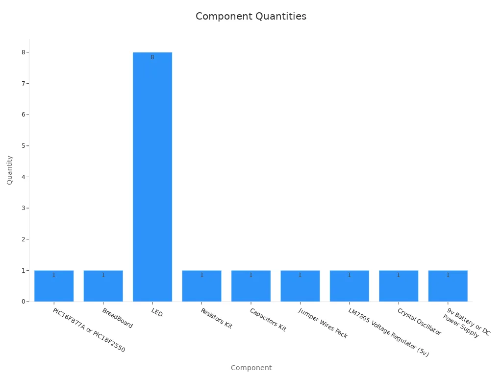
To use EEPROM with the PIC12F1822, you need some parts. These parts help build a working circuit for saving data. Below is a list of what you'll need:
Component | Quantity |
|---|---|
PIC12F1822 Microcontroller | 1 |
Breadboard | 1 |
0.1-µF Capacitors | 8 |
2.2-kΩ Resistors | 16 |
Male-Male Jumper Wires | N/A |
LM7805 Voltage Regulator (5V) | 1 |
9V Battery or DC Power Supply | 1 |
Crystal Oscillator | 1 |
For better testing, you might need tools like a Digital Storage Oscilloscope (DSO), a logic analyzer, or a PICkit programmer.
Tip: Use neat jumper wires to avoid messy connections and mistakes.
Connecting the PIC12F1822 pins
Connecting the PIC12F1822 pins correctly is very important. Follow these steps to set up the microcontroller:
Attach the VDD pin to power and the VSS pin to ground.
Connect the EEPROM's SCK, SI, and SO pins to matching microcontroller pins.
Link the CS (Chip Select) pin to a GPIO pin on the PIC12F1822. This controls when the EEPROM is active.
If using extras like a temperature sensor or LCD, connect them to GPIO pins.
Here’s a simple setup example:
The AT25010 EEPROM chip connects to SPI pins on the microcontroller.
A DS18B20 temperature sensor links to a GPIO pin for data sharing.
The Nokia5110 LCD uses SPI pins to show stored data.
Tips for power supply stability
A steady power supply is key for EEPROM to work well. Use an LM7805 regulator to keep the voltage at 5V. Place 0.1 µF capacitors near the PIC12F1822 power pins to reduce noise. If using a battery, make sure it has enough power for the circuit.
Note: Don’t cut power during writing. It can damage the saved data.
By following these steps, you can build a strong circuit for saving and reading data. This setup helps your smart sensor node work smoothly and reliably.
Save Data Using EEPROM with MPLAB XC8
Initializing EEPROM
Before saving data, you must set up EEPROM correctly. This ensures the microcontroller can work with the EEPROM module. MPLAB XC8 offers different ways to do this, depending on your needs.
For 8-bit devices, use the __EEPROM_DATA() macro to set starting values in EEPROM. Here’s an example:
#include <xc.h>
__EEPROM_DATA(0, 1, 2, 3, 4, 5, 6, 7);
This code fills the first eight EEPROM slots with values from 0 to 7. If you prefer assembly language, use the DE directive to set data in EEPROM memory:
EEPROM CODE 0x2100
DE "MCHP"
These methods let you store default settings or calibration data in EEPROM before running your program.
Tip: Check your setup code to ensure it works with your microcontroller, like the PIC12F1822-I/SN. This microcontroller has built-in EEPROM, 1PWM output, and a fast ADC module, making it great for smart sensor projects.
Writing Data to EEPROM
To save data in EEPROM, send the data to a specific memory spot. MPLAB XC8 makes this easy with built-in functions. Follow these steps:
Start I2C with
I2C1_Init(100000);.Begin communication using
I2C1_Start();.Send the device address with
I2C1_Wr(0xA0);.Pick the EEPROM address using
I2C1_Wr(Address1);andI2C1_Wr(Address2);.Write the data using
I2C1_Wr(Data);.End communication with
I2C1_Stop();.
Here’s a table of the steps:
Step | Description |
|---|---|
1 | Start I2C with |
2 | Begin I2C communication with |
3 | Send device address using |
4 | Choose EEPROM address with |
5 | Save data using |
6 | End I2C communication with |
For example, to save 0x55 at address 0x10, use this code:
I2C1_Init(100000);
I2C1_Start();
I2C1_Wr(0xA0);
I2C1_Wr(0x00); // High byte of address
I2C1_Wr(0x10); // Low byte of address
I2C1_Wr(0x55); // Data to write
I2C1_Stop();
Note: Don’t write to the same spot too often. This helps your EEPROM last longer by reducing wear.
Reading Data from EEPROM
To read data from EEPROM, follow similar steps as writing, but instead of sending data, you’ll retrieve it. Here’s how:
Start I2C communication with
I2C1_Start();.Send the device address using
I2C1_Wr(0xA0);.Pick the EEPROM address with
I2C1_Wr(Address1);andI2C1_Wr(Address2);.Restart communication with
I2C1_Start();.Send the read address using
I2C1_Wr(0xA1);.Read the data using
I2C1_Rd(0);.End communication with
I2C1_Stop();.
Here’s an example to read data from address 0x10:
I2C1_Start();
I2C1_Wr(0xA0);
I2C1_Wr(0x00); // High byte of address
I2C1_Wr(0x10); // Low byte of address
I2C1_Start();
I2C1_Wr(0xA1);
unsigned char data = I2C1_Rd(0);
I2C1_Stop();
The variable data now holds the value from EEPROM. You can use this data for tasks like showing sensor readings or restoring settings.
Tip: Always check if the data in EEPROM matches what you expect. This ensures your smart sensor works correctly.
By following these steps, you can easily save and read data using EEPROM. The PIC12F1822-I/SN’s built-in EEPROM, 1PWM output, and fast ADC module make it a great choice for smart sensor projects.
Best practices for efficient usage
Using EEPROM wisely helps it last longer and work better. Follow these tips to make the most of it:
Limit Writing Often
EEPROM cells can only handle so many writes. Writing too much wears them out. Only save data when it changes. For example, check if a sensor reading is new before saving it.Tip: Use a temporary storage area in your code. Save to EEPROM only when this storage fills up.
Spread Out Writes
Don’t always write to the same spot. Use different addresses to avoid wearing out one area. This method, called wear leveling, keeps EEPROM healthy.// Example: Spread out writes unsigned char address = (base_address + offset) % 256; EEPROM_Write(address, data);Write Safely with Power
Keep power steady when saving data. Losing power during writing can ruin the data. Add capacitors near the microcontroller to help. If using batteries, check their charge and avoid writing when they’re low.Organize Memory Well
Plan where to store different data types in EEPROM. For example, use one section for settings and another for sensor readings. This makes your project easier to manage.Data Type
Memory Range
Sensor Settings
0x00 - 0x0F
Calibration Data
0x10 - 0x1F
Sensor Readings
0x20 - 0xFF
Check Stored Data
After saving, read the data back to ensure it’s correct. This is important for projects needing accurate information. You can add error-checking methods like checksums to find mistakes.Speed Up Your Code
Saving to EEPROM takes time. Write your code to avoid slowing down your project. For example, save data when the microcontroller isn’t busy.Note: Check the PIC12F1822 datasheet for how long writing takes.
Backup Critical Data
For important information, save a copy on another device. This way, you won’t lose it if something goes wrong.
By following these steps, you can use EEPROM efficiently. The PIC12F1822 microcontroller, with its built-in EEPROM, is a great choice for saving data in smart sensor projects.
Practical Application: Smart Sensor Node
Example with a temperature sensor
Think about making a smart sensor to check greenhouse temperatures. A DS18B20 sensor can measure the temperature and send it to the PIC12F1822 microcontroller. The microcontroller saves this data in its EEPROM memory. This keeps the data safe even if the power goes out.
Using EEPROM here has many benefits. It lets you save important data, like temperature limits or calibration settings, directly on the sensor. This reduces the need to always connect to external servers, saving power and making the system more efficient.
In a test, a system with a temperature sensor worked with 99.87% efficiency. Over 8 hours, it created 2,364 data packets. Even in tough conditions, it recovered lost packets and kept working well. This shows how reliable EEPROM-based systems are for saving data in hard situations.
Storing sensor data in EEPROM
To save temperature data in EEPROM, write it to specific memory spots. For example, use one byte of memory for each reading. The PIC12F1822’s EEPROM has 256 bytes, enough for small projects like this.
Here’s how to save data in EEPROM:
Get the temperature reading from the sensor.
Change the reading into a storable format, like an integer.
Save the data to the next free memory spot in EEPROM.
A study compared memory types for IoT nodes. Nodes with F-RAM sent 124,416 samples daily, while EEPROM nodes sent 13,824. However, EEPROM nodes had data issues due to limited write cycles. This shows why wear-leveling methods are needed to make EEPROM last longer and store data reliably.
IoT Node | Samples received / day |
|---|---|
with F-RAM | 124,416 |
without Memory | 41,472 |
with EEPROM | 13,824 (data issues) |
To use EEPROM better, avoid writing to the same spot often. Use a circular buffer or wear-leveling to spread writes across memory. This reduces wear and helps EEPROM last longer.
Retrieving data for IoT applications
After saving temperature data in EEPROM, you can read it later for analysis or sharing with IoT platforms. To do this, read the data from its memory spot. Then, send it to a local or online server for further use.
For example, use the data to send alerts if the temperature gets too high. This is helpful in greenhouses where keeping the right temperature is key for plants.
In the same study, the system recovered lost packets during data sharing. It lost eight packets on a local server and 174 online but got them back. This shows how important strong data management is when using EEPROM for IoT.
By mixing EEPROM with IoT, you can make smart sensors that are reliable and efficient. The PIC12F1822’s built-in EEPROM is a great choice for these projects. It’s small, affordable, and perfect for saving and using important data.
Testing and Debugging EEPROM
Checking Read and Write Functions
Testing EEPROM read and write ensures data stays correct. Use commands like setest to check stored data. This command writes test data, reads it back, and compares it. If the data matches, the EEPROM works fine.
Follow these steps to keep data reliable:
Check stored data often by reading and comparing it.
Refresh data by rewriting it sometimes to avoid memory damage.
For example, write a value to a memory spot, read it back, and compare. If they match, the operation worked. This is helpful when using external EEPROM with the PIC12F1822 microcontroller.
Fixing Common Problems
Problems like data errors or memory wear can happen with EEPROM. Use wear-leveling and error correction to fix these. Wear-leveling spreads writes across memory to avoid overusing one spot. Static wear-leveling tracks usage and stops using worn-out blocks.
Error correction, like Hamming codes, fixes small data errors. Some EEPROMs show a flag when errors are fixed. This helps you check memory health and act early.
A static wear-leveling flowchart uses checks and rewrites for reliability. It finds unused bits, updates counts, and rewrites blocks to EEPROM.
When using external EEPROM, check connections and keep power steady. Unstable power can cause incomplete writes and data errors.
Debugging Tools and Tips
Modern tools make fixing EEPROM problems easier. For the PIC12F1822, try these methods:
Method | What It Does |
|---|---|
Breakpoints | Stop the program at certain points to check its state. |
Watchpoints | Track changes in variables to see how data moves and changes. |
MPLAB X IDE | Change and watch program behavior live to find and fix issues faster. |
These tools are great for external EEPROM. For example, use a breakpoint at the write function to check sent data. Watchpoints can warn you about unexpected variable changes, helping you find problems.
By using these tools and writing good code, you can build a strong and reliable EEPROM system.
Using EEPROM with the PIC12F1822 means knowing its features, building the circuit, and writing simple code to manage data. You learned how to set it up, save, and read data while using smart tips to make EEPROM last longer.
Adding EEPROM to smart sensors keeps data safe, even if power goes out. It makes your design easier by needing fewer extra parts and works well with low-power devices.
Resources to learn more:
PIC12F1822 Datasheet
MPLAB XC8 Compiler Guide
Microchip’s notes on using EEPROM.
Check these links to learn even more!
FAQ
What does EEPROM do in a PIC microcontroller?
EEPROM keeps data safe even when the power is off. It stores things like sensor readings, settings, or calibration data. This helps your smart sensor work reliably by saving important information.
How can you save data to EEPROM in a PIC microcontroller?
Use MPLAB XC8 functions to write data to EEPROM. Pick a memory spot first, then send the data there. Don’t write too often to the same spot to make EEPROM last longer.
Is the PIC12F1822 good for IoT projects?
Yes, the PIC12F1822 works well for IoT devices. Its EEPROM lets you save sensor data directly on the microcontroller. Later, you can read this data or send it to IoT platforms. It’s great for battery-powered gadgets because it uses little energy.
How can you keep EEPROM data safe?
Check the data after saving it to make sure it’s correct. Use error-checking tools like checksums. Don’t lose power while saving data. For very important information, save a copy in another memory spot.
What are EEPROM’s limits in a PIC microcontroller?
EEPROM can only handle about 1,000,000 writes before wearing out. It also has small storage, like 256 bytes in the PIC12F1822. Plan carefully to avoid using up all the space.
See Also
Managing Data Storage and Configuration for Smart Home Chips
Ensuring Reliable Data Storage Through W25Q128FVSIG Programming
Enhancing Smart Sensor Performance with ATMEGA328PB-AU
Achieving Effective SPI Communication Using W25Q32JVSSIQ Chip

© Copyright 205 Zhongdeyuan (Hong Kong) Technology Co., Limited - All Rights Reserved.