Programming the W25Q128FVSIG for Reliable Data Storage

The W25Q128FVSIG SPI interface NOR Flash storage chip is excellent for storing data. It performs efficiently in small electronic systems and devices. With a clock speed of 104 MHz, the W25Q128FVSIG can operate quickly. When reading data, the chip consumes up to 25 mA. It is capable of being programmed or erased approximately 100,000 times and ensures data retention for up to 20 years. Its straightforward design makes it user-friendly for integration into small gadgets.
Key Takeaways
The W25Q128FVSIG chip stores data safely for up to 20 years. It can handle 100,000 write and erase cycles.
Set it up correctly. Use a 3.3V power supply and connect SPI wires securely to avoid problems.
Always check saved data by reading it back. Use checksums to find mistakes.
Spread out writing across memory blocks to make the chip last longer. This is called wear leveling.
Check the power supply and connections often. This helps stop data loss and keeps it working well.
Understanding the W25Q128FVSIG
Key Specifications and Features
The W25Q128FVSIG SPI NOR Flash chip is great for small systems. It stores up to 128 megabits, which fits many needs. Its SPI interface runs fast, with speeds up to 104 MHz. The chip lasts long, handling 100,000 program/erase cycles. It keeps data safe for up to 20 years.
It also has dual and quad SPI modes for better speed. The chip works with voltages from 2.7V to 3.6V. This makes it usable in many devices. Its low power use helps save energy, even in gadgets with batteries.
Feature | W25Q128FVSIG | Similar Solutions |
|---|---|---|
Data Retention | Up to 20 years | Often shorter |
Endurance Ratings | 100,000 program/erase cycles | Usually lower |
Operational Characteristics | High-speed SPI interface | May lack SPI support |
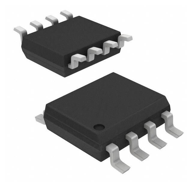
Pinout and Functional Overview
The W25Q128FVSIG has 8 pins, making it simple to connect. Each pin has a job:
CS (Chip Select): Starts communication with the chip.
DO (Data Out): Sends data during reads.
DI (Data In): Takes data during writes.
CLK (Clock): Keeps data transfer in sync.
WP (Write Protect): Stops unwanted changes to data.
HOLD: Pauses communication without resetting the chip.
VCC and GND: Provide power and ground.
This pin layout makes it easy to use with microcontrollers.
Highlights from the Datasheet
The datasheet explains the W25Q128FVSIG features well. It shows how wear leveling and ECC keep data accurate. The memory is split into 16 sectors, 256 blocks, and 16 pages per block. This setup makes storing and finding data easier.
It also talks about the chip's standby mode, which saves power when idle. The datasheet says it works in different temperatures, so it performs well in many places.
Setting Up the Hardware
Required Components and Tools
Before using the W25Q128FVSIG, gather all needed items. You will need:
A W25Q128FVSIG chip.
A microcontroller or board with SPI (like Arduino or Raspberry Pi).
A breadboard for easy connections.
Jumper wires to link components.
A 3.3V power supply.
A multimeter to test connections.
An SPI programmer or USB-to-SPI adapter for computer use.
These tools make setup easier. Check if your microcontroller supports SPI. SPI is necessary to work with this chip.
Circuitry and SPI Connections
To connect the W25Q128FVSIG, set up the SPI interface. Follow these steps:
Place the chip on the breadboard.
Connect the CS pin to a GPIO pin on your microcontroller. This pin starts communication.
Link the CLK pin to the SPI clock pin on your microcontroller.
Attach the DI pin to the SPI MOSI pin.
Connect the DO pin to the SPI MISO pin.
Ground the GND pin and provide 3.3V to the VCC pin.
Tip: Use short jumper wires. This reduces noise and keeps communication stable.
Power Supply Considerations
The W25Q128FVSIG works with 2.7V to 3.6V. Use a 3.3V power supply to avoid damage. If your microcontroller uses 5V, add a level shifter to protect the chip. Use a multimeter to check the voltage stays steady.
A good power source is very important. Avoid weak batteries that might run out fast. Low power can stop data transfers and cause problems.
Programming the W25Q128FVSIG SPI Interface NOR Flash Storage Chip
Writing Data to the Chip
To save data on the W25Q128FVSIG, follow these steps carefully. Writing data means preparing the chip, erasing parts, and checking the saved data. Here’s how to do it:
Enable Writing: Turn on the chip for saving data by sending a command.
Erase Register: Clear the register to make space for new data. This sets it to 0xFF.
Read Register: Copy the current data from the register into a temporary storage.
Change Data: Update the temporary storage with the new information.
Enable Writing Again: Allow the chip to save the updated data.
Save Data: Write the new information back into the register.
Check Data: Read the register again to ensure the data saved correctly.
The table below explains each step in detail:
Step | Action | Value0 | Value1 | Comment |
|---|---|---|---|---|
0 | Start Communication | -- | -- | Turn on Chip Select to begin communication |
1 | Send Write Command | 1 | 06 | Enable writing to the chip |
2 | Stop Communication | -- | -- | Turn off Chip Select |
3 | Start Communication | -- | -- | Turn on Chip Select again |
4 | Erase Register | 4 | 44,00,10,00 | Clear the register for new data |
5 | Stop Communication | -- | -- | Turn off Chip Select |
6 | Wait | 200ms | -- | Pause while the register clears |
7 | Start Communication | -- | -- | Turn on Chip Select again |
8 | Read Register | 4 | 48,00,10,00 | Get the current register data |
9 | Send Dummy Clocks | 1 | FF | Send extra clock signals |
10 | Save Data to Buffer | 0 | 16 | Store 16 bytes into temporary storage |
11 | Stop Communication | -- | -- | Turn off Chip Select |
Tip: Always check the saved data by reading it back. This avoids errors and keeps your data safe.
Reading Data from the Chip
Getting data from the W25Q128FVSIG is simple. Use the SPI interface to read stored information. Follow these steps:
Start Communication: Turn on Chip Select to begin talking to the chip.
Send Read Command: Tell the chip which memory address to read.
Send Dummy Clocks: Add extra clock signals to prepare the chip.
Get Data: Read the data into your microcontroller or temporary storage.
Here’s an example of how to read data using code:
// Example: Reading data from W25Q128FVSIG
digitalWrite(CS_PIN, LOW); // Start communication
SPI.transfer(READ_COMMAND); // Send read command
SPI.transfer(MEMORY_ADDRESS); // Choose memory address
byte data = SPI.transfer(0x00); // Get data
digitalWrite(CS_PIN, HIGH); // Stop communication
Note: Make sure the SPI clock speed matches the chip’s needs for best results.
Dumping the Firmware Image
Dumping the firmware image means copying all the chip’s data. This helps you back up or study the stored information. Use tools like flashrom to make this process easier. Here’s how:
Install flashrom: This tool helps copy the chip’s data. Connect the chip to your computer using an SPI programmer.
Set Speed: Choose the SPI speed (e.g.,
spispeed=8000) for faster copying.Find the Chip: If flashrom doesn’t detect the chip, manually add its name using the
-coption.Copy Multiple Times: Repeat the process to ensure the data is correct. Compare checksums to confirm accuracy.
Tip: Always check the copied firmware image. Comparing checksums ensures the data is correct and ready for use.
By following these steps, you can safely copy and use the chip’s data.
Ensuring Data Reliability
Best Practices for Error Handling
Using the W25Q128FVSIG chip needs careful error handling. Follow these tips to avoid problems:
Check Status Registers: Look at the chip's status registers before and after tasks. These show if the chip is ready or has errors.
Retry Failed Tasks: If reading or writing fails, try again. This helps fix temporary issues.
Set Time Limits: Use timeouts for writing or erasing. This stops your system from freezing if the chip stops responding.
Protect Important Data: Turn on the Write Protect (WP) pin. This keeps key memory areas safe from changes.
Prepare for Power Loss: Add capacitors or backup power. This lets the chip finish tasks during sudden power cuts.
Tip: Test your error-handling steps often. Make sure they work in different situations.
Techniques for Verifying Data Integrity
Keeping your data accurate is very important. The W25Q128FVSIG chip has tools to help check data. Try these methods:
Check After Writing: Write data, then read it back to compare. This ensures the data saved correctly.
Use ECC: The chip has Error Correction Code (ECC). It fixes small errors when reading. Enable this feature in your setup.
Create Checksums: Make a checksum or hash before saving data. After reading, create it again and compare. This finds errors easily.
Regular Data Checks: Read and verify stored data often. This catches and fixes errors caused by time.
Note: Using more than one method adds extra safety for your data.
Wear Leveling and Memory Endurance Tips
The W25Q128FVSIG chip can handle about 100,000 write/erase cycles. To make it last longer, use wear leveling. Here’s how:
Spread Out Usage: Don’t write to the same spot repeatedly. Use methods that spread tasks across the chip.
Choose Smart File Systems: Use file systems like YAFFS or JFFS2. They include wear leveling to protect memory.
Track Usage: Watch how often each memory block is used. This helps find overused areas.
Keep Spare Blocks: Save some memory as spares. These replace worn-out blocks and extend the chip’s life.
Tip: Update your firmware often. New updates may include better wear leveling methods.
By following these steps, your W25Q128FVSIG chip will stay reliable and work well for a long time.
Troubleshooting Common Issues
Fixing SPI Communication Problems
SPI problems can stop data transfer between your microcontroller and the W25Q128FVSIG chip. Here’s how to fix common issues:
Wrong data might be read. For example, some users get a Manufacturer ID of 0xDC instead of 0xEF. This happens when the address byte order is wrong.
Clock speed mismatches can cause errors. Make sure the SPI clock matches the chip’s needs.
Loose wires or bad connections can break signals. Check all wires, especially the CS line.
To solve these, use a logic analyzer to check SPI signals. Look at the timing and commands sent to the chip. If byte order is wrong, adjust your microcontroller’s SPI settings.
Fixing Write and Read Errors
Write and read errors can stop data from saving or loading. Fix them with these steps:
Check Software: Make sure tools like flashrom work with the chip. Check your code for correct memory handling.
Fix Write/Erase Issues: Check the chip’s limits. Always send the write enable command before saving. Use the right erase commands for clearing memory.
Inspect Connections: Look at all wires, especially the CS line and power pins. Loose wires can cause errors.
Check Power Supply: Use a multimeter to measure voltage. The chip needs a steady 3.3V. Add capacitors to reduce noise.
If problems continue, try another microcontroller or SPI programmer to check for hardware issues.
Solving Power Problems
Power issues can make the chip work poorly. Follow these tips for stable power:
Use a steady 3.3V power source. Avoid weak batteries that drain fast.
Check grounding wires. Bad grounding can cause noise and errors.
Add capacitors near the chip to smooth voltage changes. This keeps power steady during fast operations.
If the chip doesn’t work, check for voltage drops during SPI use. Replace weak power sources or bad regulators to fix the problem.
Using the W25Q128FVSIG chip needs careful steps. First, set up the hardware properly. Then, connect the SPI interface securely. Follow simple rules for saving and reading data. Handle errors well to keep the chip working. Use wear leveling to make it last longer. Always check your data to avoid mistakes.
To learn more, read the datasheet, example code, and libraries. These tools will teach you how to use the chip better and improve your projects.
FAQ
What does the W25Q128FVSIG chip do?
The W25Q128FVSIG chip stores data for small systems. It holds up to 128 megabits and uses fast SPI communication. Its long-lasting design makes it great for IoT, gadgets, and industrial tools.
Can I connect a 5V microcontroller to the W25Q128FVSIG?
Yes, but you need a level shifter. This device safely links the 5V microcontroller to the chip’s 3.3V system. It protects the chip and keeps communication working.
How can I check if data saved correctly?
After saving data, read it back and compare it. You can also use checksums or hashes to check for errors. The chip’s ECC feature fixes small mistakes when reading data.
What tools do I need to program the W25Q128FVSIG?
You’ll need a microcontroller or SPI programmer, jumper wires, and a breadboard. A 3.3V power supply and a multimeter are also important. Software like flashrom helps with programming and copying firmware.
How do I make the W25Q128FVSIG last longer?
Use wear leveling to spread out memory use. Don’t write to the same spot too often. File systems like YAFFS or JFFS2 help protect memory by balancing usage.
Tip: Check memory use often. This helps find overused areas and avoids early damage.
See Also
Understanding SPI Communication Using The W25Q32JVSSIQ Chip
The W25Q256JVEIQ: An Excellent Choice For Embedded Applications
Choosing The XCF04SVOG20C Chip For 4Mb Configurations

© Copyright 205 Zhongdeyuan (Hong Kong) Technology Co., Limited - All Rights Reserved.