How to Achieve Reliable Data Transmission with MAX485ESA

Reliable data transfer makes sure information moves without mistakes. In RS-485 communication, this is very important, especially for factories or long-distance networks. RS-485 can connect 32 devices or up to 256 with repeaters. It keeps signals strong even when many devices are connected.
The MAX485ESA module helps make serial communication reliable. It uses differential signaling to send data up to 1200 meters with little interference. With a speed of 2.5 Mbps and support for 32 receivers, it ensures smooth and steady data transfer.
To use the MAX485ESA, connect its pins properly, set baud rates, and check grounding. These steps help build a strong RS-485 communication system.
Key Takeaways
Sending data without mistakes is important for RS-485 communication. This is especially true in factories or industrial places.
The MAX485ESA module helps send data well by using special signals. It can send data up to 1200 meters with little trouble from outside noise.
To set up the MAX485ESA, connect the pins correctly. Match the baud rates and make sure the grounding is done right for a strong system.
Using twisted-pair wires and resistors improves the signal and cuts down noise. This makes RS-485 networks work better.
Checking and fixing your RS-485 system often can stop problems. This keeps your communication steady and working well for a long time.
Understanding RS-485 and MAX485ESA
Overview of RS-485 Communication
RS-485 is a strong communication system for sending data far. It uses special signaling to block noise and keep signals clear. This makes it great for factories where interference happens often. RS-485 lets many devices share one connection line. Popular systems like Modbus and Profibus use RS-485 because it works well and is dependable.
RS-485 also uses encoding methods like NRZ and Bi-phase. NRZ shows data with high or low voltage levels. Bi-phase helps keep timing and sync steady. RS-485 also has a feature to ignore equal voltages on both lines. This improves how well it works in noisy areas.
Benefits of RS-485 for Serial Communication
RS-485 has many advantages over other systems. It can send data up to 4,000 feet, which is farther than most. It also sends data fast, up to 10 Mbps, making it good for quick tasks. RS-485 connects up to 32 devices on one line, which is great for big setups.
Feature | RS-485 | Other Protocols |
|---|---|---|
Maximum Distance | Up to 4,000 feet | Less than 1,000 feet |
Data Transmission Speed | Up to 10 Mbps | Often slower |
Multi-device Connectivity | Up to 32 devices | Fewer devices |
Resistance to Electrical Noise | High due to special signaling | Often lower |
Cost-effectiveness | Few extra parts needed | Needs more parts |
These features make RS-485 a smart and reliable choice for long-distance communication in factories and businesses.
Features and Role of the MAX485ESA Module
The MAX485ESA module is important for RS-485 communication. It changes signals between TTL and RS-485 formats. It supports half-duplex, so devices can send and get data on one line. Its special signaling reduces interference, even over long distances.
The MAX485 works at speeds up to 2.5 Mbps and uses 5V power. It has features like protection from shocks up to ±15kV and low power use of 300µA. It also has fail-safe receivers to avoid errors. Its small size and ability to work in extreme temperatures (-40°C to +85°C) make it very useful.
Feature | Specification |
|---|---|
Interface Type | RS-485 / RS-422 |
Data Rate | Up to 2.5 Mbps |
Supply Voltage | 5V |
Operating Temperature | -40°C to +85°C |
Packaging | 8-SOIC |
ESD Protection | Up to ±15kV |
Low Quiescent Current | 300µA |
Half-Duplex Communication | Yes |
Current-Limiting Protection | Yes |
Fail-Safe Receiver | Yes |
Using the MAX485 module helps create strong and efficient RS-485 systems for many uses.
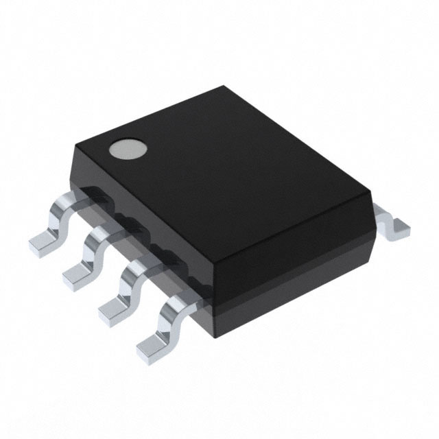
Pinout and Specifications of MAX485ESA
Knowing the pinout of the MAX485ESA is very important. It helps you set up your RS-485 system correctly. This module has 8 pins, and each pin has a job. Below is a simple explanation of the pins:
Pin 1 (RO): This pin gives the received data in TTL form.
Pin 2 (RE): Set this pin low to turn on the receiver. If high, the receiver turns off.
Pin 3 (DE): Set this pin high to turn on the driver. If low, the driver turns off.
Pin 4 (DI): This pin takes the data you want to send.
Pin 5 (GND): Connect this pin to your circuit's ground.
Pin 6 (A): This is one of the signal lines for sending or receiving data.
Pin 7 (B): This is the opposite signal line to Pin 6.
Pin 8 (VCC): Provide 5V power to this pin.
Tip: Check your connections carefully to avoid damage to the module or circuit.
The MAX485ESA works well in many conditions. Its features make it great for factories and businesses. Here's a quick summary:
Specification | Details |
|---|---|
Operating Voltage | 5V |
Data Rate | Up to 2.5 Mbps |
ESD Protection | ±15kV |
Operating Temperature | -40°C to +85°C |
Communication Mode | Half-Duplex |
By learning the pinout and features, you can use the MAX485ESA easily. Correct wiring and setup will ensure smooth and reliable data transfer.
Setting Up MAX485ESA for RS485 Communication
Components and Tools Needed
To use the MAX485ESA for RS485, you need some tools. These items help ensure smooth and reliable data transfer. Here's what you'll need:
MAX485ESA module: The main part for RS485 communication.
Microcontroller: Sends and receives data, like Arduino or Raspberry Pi.
Power Supply: Provides a steady 5V power for the module.
Resistors: Use 120-ohm resistors to stop signal reflections.
Wires and Connectors: For secure and proper connections.
Multimeter: Checks connections and measures voltage levels.
Oscilloscope: Optional but helps check signal quality.
Below is a table showing key details of the MAX485ESA module:
Item | Value |
|---|---|
Operating Supply Voltage | 3.3V |
Data Rate | 2.5Mbps |
Number of Receivers | 32 |
Storage Temperature Range | -65 to 160℃ |
Channel Number | 8 |
Resolution | 12-Bit |
Power Consumption | Changes with data speed |
Size | 62mm x 39.2mm x 21.8mm |
Weight | 23g |
Wiring and Connections for MAX485ESA
Good wiring is key for RS485 to work well. First, connect the VCC pin of the MAX485 to a 5V power source. Then, link the GND pin to the ground. Attach the A and B pins to the RS485 network wires. Use the DI pin to send data and the RO pin to receive it. Control the DE and RE pins to switch between sending and receiving.
Tip: Use short, twisted wires for A and B to reduce noise.
Importance of Grounding and Termination Resistors
Grounding and resistors are very important in RS485 systems. Grounding lowers noise and keeps data stable. Termination resistors, usually 120 ohms, match the cable's impedance. This stops signal reflections that can mess up communication.
Here’s a table summarizing grounding and resistor tips:
Evidence Description | Key Points |
|---|---|
Ground Loop Sensitivity | Grounding lowers noise problems. |
Termination Resistors | Stops reflections by matching cable impedance. |
Common-Mode Noise Filtering | Filters improve performance in noisy places. |
By following these steps and using the right tools, you can set up a strong RS485 system.
Configuring Baud Rate and Direction Control
Setting the right baud rate and controlling direction are key steps. These settings help devices send and receive data without errors.
Setting the Baud Rate
The baud rate shows how fast data moves between devices. Both sender and receiver must use the same baud rate. If they don’t match, data can get lost or damaged. The UART interface depends on this match to work well.
Here are some simple facts about baud rate:
Devices need the same baud rate for smooth communication.
A mismatch over 10% can cause timing problems and errors.
Common baud rates are 9600, 19200, and 115200 bps. Pick one that fits your system.
Tip: If you have issues, check the baud rate with a multimeter or oscilloscope.
Managing Direction Control
Direction control is very important in RS-485 systems. This is especially true for half-duplex setups. The MAX485ESA module uses DE (Driver Enable) and RE (Receiver Enable) pins. These pins switch between sending and receiving modes. Setting them right stops devices from clashing during data transfer.
Turn the DE pin high to send data.
Turn the RE pin low to receive data.
In full-duplex systems, direction control matters less. Separate lines handle sending and receiving.
Good direction control avoids data clashes and keeps communication smooth. By setting the baud rate and direction control correctly, your system will work better and more reliably.
Note: Test your setup after making changes. This helps find and fix problems early.
Software Setup for MAX485ESA
Choosing Libraries for RS485 Communication
To set up the MAX485ESA, you need helpful software libraries. These libraries make it easier for your microcontroller to talk to the RS485 network. If you use an Arduino, try the "Arduino RS485" library. It has tools to send and receive data easily. For advanced boards like the ESP32, use the "ESP32 Modbus Master-Slave" library. This library works with RS485 and supports industrial systems like Modbus.
When picking a library, make sure it works with your microcontroller. Check if it allows baud rate settings and direction control. A good library should also handle errors to keep data transfer smooth. You can find these libraries in the Arduino IDE Library Manager or on GitHub.
Tip: Read the library guide. It explains how to use the tools properly.
Writing Code to Send Data
After choosing a library, you can write code to send data. First, include the library in your program. Then, set up RS485 communication by choosing a baud rate and turning on the driver pin. Use the library’s write() or send() function to send messages.
Here’s an example for Arduino:
#include <RS485.h>

void setup() {
  RS485.begin(9600); // Set baud rate
  pinMode(2, OUTPUT); // Driver enable pin
}

void loop() {
  digitalWrite(2, HIGH); // Turn on driver
  RS485.write("Hello, RS485!"); // Send message
  delay(1000); // Wait before sending again
}
This code sends "Hello, RS485!" every second. Change the baud rate or message to fit your needs.
Writing Code to Receive Data
Receiving data with the MAX485ESA is also simple. Turn on the receiver pin and use the library’s read() function to get incoming data. Here’s an example for Arduino:
#include <RS485.h>

void setup() {
  RS485.begin(9600); // Set baud rate
  pinMode(3, OUTPUT); // Receiver enable pin
}

void loop() {
  digitalWrite(3, LOW); // Turn on receiver
  if (RS485.available()) { // Check for data
    char received = RS485.read(); // Get data
    Serial.print("Received: ");
    Serial.println(received);
  }
}
This code listens for data and shows it in the Serial Monitor. Make sure the baud rate matches the sender’s settings.
Note: Test your program with a working RS485 device to confirm it works.
Explanation of Code Functionality
Knowing how the code works helps use the MAX485ESA better. The examples above show how to send and receive data using RS-485. Let’s explain each part step by step.
Sending Data
The sending code starts RS-485 communication by setting the baud rate. It also sets the driver pin to control data sending. When the driver pin is HIGH, the MAX485ESA sends data. The RS485.write() function sends the message through RS-485. After sending, turn off the driver pin to save power.
Tip: Always set the driver pin HIGH before sending. This avoids errors.
Receiving Data
The receiving code listens for messages. It sets the receiver pin to LOW, turning on receive mode. The RS485.available() function checks if data is on the network. If data exists, the RS485.read() function gets it. The code shows the received message, making it easy to check communication.
Note: The sender and receiver must use the same baud rate for correct data transfer.
Key Features of RS-485 Code
The MAX485ESA module has many useful features. Below is a summary of its abilities:
Feature | Description |
|---|---|
Temperature Range | Works between -65°C and 160°C |
Number of Channels | Has 8 channels |
Resolution | Offers 12-bit resolution |
Energy Consumption | Changes with data speed |
Dimensions | Measures 62 x 39.2 x 21.8 mm |
Weight | Weighs 23 g |
Typical Applications | Used in RS-485 systems, converters, factories, and semi-duplex setups |
Chip Used | Uses the MAX485ESA chip |
GPIO Pins Used | Uses GPIO14 (DI), GPIO15 (RO), GPIO18 (RE/DE) |
Communication Test Code | Includes Python examples for sending and receiving RS-485 data |
Setup Instructions | Provides steps to connect RS-485 Shield to Raspberry Pi and test communication |
By learning these features and how the code works with the MAX485ESA, you can create strong RS-485 systems. Always test your setup to ensure it works properly.
Testing and Fixing RS485 Communication
Checking the MAX485ESA Setup
Testing your MAX485ESA setup makes sure it works well. First, check all connections. Look at the wiring between the module and your microcontroller. Ensure the VCC and GND pins are connected to the power supply. Confirm the A and B lines are firmly linked to the RS-485 network.
Use a multimeter to check voltage levels. The A and B lines should show about 200 mV or more when active. If you have an oscilloscope, check the signal quality. The signals should look like clean square waves without any distortion.
Next, test sending data. Send a simple message from your microcontroller. Check if the receiving device shows the correct message. If it doesn’t, review the baud rate, direction control, and termination resistors.
Tip: Always test your setup in a safe place before using it elsewhere.
Solving Common RS485 Problems
RS-485 systems can face problems. Signals may weaken over long cables due to resistance and capacitance. Noise can also disrupt communication, especially in factories. High slew rates might cause electromagnetic interference (EMI), making things worse.
Here’s a table of common problems and their causes:
Problem | Cause |
|---|---|
Weak Signals | Long cables cause resistance and capacitance issues. |
Noise and Interference | Electrical noise can corrupt data on longer cables. |
EMI Issues | High slew rates create EMI, affecting communication reliability. |
To fix these, use twisted-pair cables to reduce noise. Add termination resistors to stop signal reflections. For EMI, lower the slew rate or use shielded cables.
Fixing RS485 Errors
If errors happen, find the problem step by step. Check the wiring for loose or wrong connections. Make sure the A and B lines are not swapped. Verify that all devices share the same ground.
If the wiring is fine, check the software settings. Ensure all devices use the same baud rate. Test the DE and RE pins to confirm they switch properly between sending and receiving.
For tough problems, use tools like an oscilloscope to spot signal issues. A logic analyzer can help track data flow and find errors. Adjusting termination or adding biasing resistors might also help.
Note: Regular checks and tests can stop many RS-485 problems before they start.
Tips for Better Communication Reliability
To make RS-485 networks work well, follow these simple tips. They help keep data transfer smooth and error-free.
Use the Right Termination Resistors: Match resistors to your cable's impedance. This stops signal reflections that can mess up data. A 120-ohm resistor usually works for most RS-485 cables.
Ground Your System Properly: Grounding stops interference in noisy places like factories. Connect all devices to the same ground to avoid errors and keep things stable.
Pick Twisted-Pair Cables: These cables block electromagnetic interference (EMI). They also reduce signal problems, making data clearer. Keep cables short for better performance.
Tip: Don’t place RS-485 cables near high-power equipment. This helps avoid interference that can break communication.
Adjust Slew Rates: High slew rates may cause noise in long setups. Set the rate to fit your system. Lower rates cut noise, while higher rates send data faster.
Test Often: Regular checks find problems early. Use tools like multimeters or oscilloscopes to check signals and ensure everything works.
By using these steps, you can create a strong RS-485 network that works well even in tough conditions.
Applications and Best Practices for MAX485ESA
Real-World Uses of MAX485ESA in RS485 Networks
The MAX485ESA is very useful in RS485 networks. It helps devices talk to each other in many industries. In factories, it links sensors, controllers, and machines over long distances. It keeps data steady, even in noisy places. Many RS485 systems use the MAX485ESA for Modbus, a common factory protocol. It supports half-duplex, so devices can send and receive on one line.
You can also pair the MAX485ESA with Arduino for projects like smart homes or remote controls. It connects up to 32 devices on one line, making it great for big setups. Whether in factories, homes, or energy systems, the MAX485ESA ensures smooth and error-free communication.
Best Practices for Reliable Serial Communication
To keep serial communication reliable with the MAX485ESA, follow these tips:
Add 120-ohm resistors at both ends of the RS485 line. These stop signal echoes and match the cable's impedance.
Use a Signal Common (SC) wire for long distances. This wire helps devices stay in sync and communicate better.
Ground all devices to reduce noise and interference. A shared ground point improves stability.
Pick twisted-pair cables to block electromagnetic noise. These cables make signals clearer in noisy areas.
Test your setup often to catch problems early. Use tools like multimeters or oscilloscopes to check signals.
By following these steps, you can create a strong RS485 network that works well in different conditions.
Ensuring Long-Term Stability in RS485 Systems
To keep RS485 systems stable for a long time, take care of them. Check wires often to ensure they are secure. Replace broken cables quickly to avoid losing data. Keep the MAX485 module and other parts clean and dust-free.
Watch your RS485 system's performance regularly. Look for voltage drops or bad signals that might show issues. Update software settings when your system changes. For factories, use surge protectors to guard against power spikes.
With good care and regular testing, your RS485 system can stay reliable for years.
To set up the MAX485ESA, connect the pins properly. Set the baud rate and make sure grounding is correct. These steps help build a strong RS-485 system. Reliable data transfer needs good parts like MAX485 transceivers, 120-ohm resistors, and shielded cables like Belden 3105A.
Part | Details | Examples |
|---|---|---|
RS-485 Transceivers | Links 32 devices | MAX485, SN75176 |
Termination Resistors | 120-ohm, precise | Vishay Dale RN60 |
Shielded Cable | Twisted pair, 24 AWG | Belden 3105A |
Use a daisy chain layout and add resistors at both ends of the line. These tips keep your RS-485 network stable and working well for a long time.
FAQ
What does the MAX485ESA module do?
The MAX485ESA changes TTL signals into RS-485 signals. This allows devices to communicate over long distances. It is useful for connecting many devices in factories or smart homes. Its low energy use and ability to block noise make it great for reliable communication.
How do you hook up the MAX485ESA to a microcontroller?
Connect the VCC pin to power and the GND pin to ground. Link the DI pin to the TX pin on your microcontroller. Attach the RO pin to the RX pin. Use the DE and RE pins to manage sending and receiving data. Connect A and B to the RS-485 wires.
Tip: Check all connections carefully to avoid mistakes.
Why are termination resistors needed in RS-485 systems?
Termination resistors stop signal echoes by matching the cable's impedance. Without them, echoes can mess up data, especially on long cables. Place 120-ohm resistors at both ends of the RS-485 line for clear communication.
Can the MAX485ESA work with full-duplex communication?
No, the MAX485ESA only supports half-duplex communication. It uses one pair of wires for both sending and receiving data. You need to control the DE and RE pins to switch modes. For full-duplex, use a different RS-485 transceiver.
What baud rate should you pick for RS-485 communication?
Pick a baud rate that fits your system’s needs. Common rates are 9600, 19200, and 115200 bps. Make sure all devices use the same baud rate to avoid problems. Lower rates are better for longer distances.
Note: Try different rates to find the best one for your system.
See Also
Enhancing In-Vehicle Communication With 88E1512-A0-NNP2C000 Ethernet Access
TXS0102DCUR: Smart Level Shifter For I²C And SPI Buses
Achieve High-Speed I/O Expansion Using EPM1270T144C5N
Managing Data Storage And Configuration With AT24C02C-SSHM-T Chip
Explore ADM2682EBRIZ For Efficient Remote Monitoring And Control

© Copyright 205 Zhongdeyuan (Hong Kong) Technology Co., Limited - All Rights Reserved.