STM32F072C8T6 development case sharing supporting USB, ADC, PWM

The STM32F072C8T6 microcontroller is excellent for USB, ADC, and PWM applications, making it a fantastic choice for various projects. With the STM32F072C8T6 development case sharing supporting USB, you can easily manage complex tasks in compact systems. This microcontroller allows you to work with signals or create precise waveforms effortlessly. Its USB capability simplifies the process of connecting devices, enhancing its utility. Equipped with straightforward tools and robust features, the STM32F072C8T6 helps you accelerate project development and inspire innovative ideas. Exploring the STM32F072C8T6 with USB can ignite new design concepts.
Key Takeaways
The STM32F072C8T6 microcontroller works great for USB, ADC, and PWM projects. It can be used in many ways.
Using STM32CubeMX and STM32CubeIDE together makes setup and coding easier. This saves time and effort.
Setting the clock correctly is very important for good performance, especially for USB tasks.
Testing USB, ADC, and PWM one by one helps find problems fast. It also makes sure everything works well.
Debugging with tools like ST-Link and SWD lets you check your code live. This makes fixing issues simpler.
Setting Up the STM32F072C8T6 Development Environment
Tools and Software for STM32 Programming
To program the STM32F072C8T6, you need specific tools and software. These make development easier and help you focus on your project. Below is a table of important tools for STM32 programming:
Tool Name | What It Does | Link |
|---|---|---|
STM32CubeMX | A tool to set up STM32 microcontrollers easily. | STM32CubeMX |
STM32CubeIDE | A coding and debugging environment for STM32 microcontrollers. | STM32CubeIDE |
ST Edge AI Suite | A tool for creating AI projects on STM32 devices. | ST Edge AI Suite |
These tools are popular because they make STM32 programming simple. For example, STM32CubeIDE lets you code, debug, and test in one place. STM32CubeMX helps you set up peripherals using a visual interface.
Tip: Using STM32CubeMX with STM32CubeIDE can save you time.
Installing STM32CubeIDE and Configuring ST-Link
Installing STM32CubeIDE is simple. Follow these steps:
Download the version for your operating system from the official site.
Unzip the installer files.
Run the installer as an administrator.
Open the program after installation.
After installing, set up ST-Link to upload code to the STM32F072C8T6. Here’s how:
Connect your STM32F072C8T6 to the ST-Link V2 programmer.
Open STM32CubeIDE and pick your ST-Link device.
Refresh to find the serial number.
Load your firmware file (ELF or Hex) and click "Download."
Many users like STM32CubeIDE for its easy interface and multi-platform support. It makes programming simpler, even for beginners.
Connecting the STM32F072C8T6 to Your PC via USB
To program and debug, connect your STM32F072C8T6 to a PC using USB. Use a USB cable to link them. Make sure the microcontroller is powered and detected by your PC. If it doesn’t work, check your drivers and update the ST-Link firmware.
USB connections also let you test communication protocols like USB CDC. This is helpful for projects where the microcontroller and PC share data.
Note: Always use good-quality USB cables to avoid connection problems.
Configuring the STM32F072C8T6 for USB, ADC, and PWM

Clock and System Setup
To make the STM32F072C8T6 work well, set up its clock. The clock controls how fast the microcontroller and its parts run. First, turn on the High-Speed Internal (HSI) oscillator. This clock runs at 8 MHz and can go faster using the Phase-Locked Loop (PLL).
In STM32CubeMX, go to the "Clock Configuration" tab. Set the system clock (SYSCLK) to 48 MHz. This is the fastest speed for the STM32F072C8T6. It helps USB and other parts work better. Change the AHB and APB prescalers to match the speeds you need. For USB, make sure the clock comes from the PLL.
Tip: Check the clock tree in STM32CubeMX to avoid problems.
Pin Setup for USB, ADC, and PWM
Choosing the right pins is important for USB, ADC, and PWM. The STM32F072C8T6 has flexible pins. You can assign them based on your project needs. Here’s a comparison of the STM32F072C8T6 and another microcontroller, STM32F042G6U6:
Feature | STM32F042G6U6 | STM32F072C8T6 |
|---|---|---|
USB | Yes (full speed device) | Yes (full speed device) |
ADC | 12-bit, one channel | Up to 16 channels, 12-bit |
PWM | Advanced-control PWM timer | Supports PWM through timers |
Core | ARM Cortex-M0, 32-bit RISC | ARM Cortex-M0, 32-bit RISC |
Flash Memory | Up to 32kB | Up to 128kB |
SRAM | 6kB | 20kB |
For USB, use PA12 for D+ and PA11 for D-. These pins handle USB communication. For ADC, pick pins like PA0 for ADC_IN0. For PWM, use pins like PA8 or PA9, which work with Timer 1.
Note: Check the STM32F072C8T6 datasheet for all pin details.
Setting Up Peripherals with STM32CubeMX
STM32CubeMX makes setting up peripherals easy. Start a new project for the STM32F072C8T6. Pick the microcontroller or board you are using.
USB Setup: Turn on the USB in the "Peripherals" tab. Choose "Device Only" mode for USB. STM32CubeMX will set up the pins and clocks for you.
ADC Setup: Turn on the ADC and pick the channels you need. For example, use ADC_IN0 for one input. Set it to 12 bits for accurate readings.
PWM Setup: Turn on the timer for PWM, like Timer 1. Set it to "PWM Generation" mode. Adjust the frequency and duty cycle as needed.
After setting everything, click "Generate Code." STM32CubeMX will create code for STM32CubeIDE. It includes all drivers and setup files.
Pro Tip: Use the "Pinout & Configuration" tab in STM32CubeMX to see your pin setup and avoid mistakes.
STM32F072C8T6 Development Case Sharing Supporting USB
Setting Up USB CDC for Data Exchange
The USB CDC feature lets the STM32F072C8T6 act like a virtual COM port. This helps the microcontroller and PC share data easily. To set it up, enable USB in STM32CubeMX. Choose "Device Only" mode and select "CDC" as the class type. STM32CubeMX will assign pins like PA11 for D- and PA12 for D+ and adjust clock settings.
After generating the code, open STM32CubeIDE. Find the usb_device.c file, which has the USB setup code. Edit the CDC_Transmit_FS function to send data from the microcontroller to the PC. For example, you can send sensor data or debug messages. Test it by connecting the microcontroller to your PC with a USB cable. Use a terminal program like PuTTY or Tera Term to check the data transfer.
Tip: Set the USB clock to 48 MHz using the PLL for stable communication.
Creating and Testing USB Firmware
Making USB firmware means writing code to send and receive data. Start a project in STM32CubeIDE using the code from STM32CubeMX. Focus on the usb_device.c and usbd_cdc_if.c files. These files handle USB CDC communication.
To send data, use the CDC_Transmit_FS function. To receive data, use the CDC_Receive_FS function. Add code to process incoming data, like commands or sensor readings. For instance, you can write firmware to read ADC values and send them to the PC through USB.
Testing is important. Connect the STM32F072C8T6 to your PC and open a terminal program. Send test data from the microcontroller and check if the PC receives it. Also, send data from the PC and ensure the microcontroller processes it. Use STM32CubeIDE debugging tools to check variables and interrupts during communication.
Note: Test with different data sizes to ensure the firmware works well.
Fixing USB Communication Problems
USB issues can happen due to hardware, firmware, or settings. Follow these steps to fix them:
Check Power: Make sure the microcontroller gets enough power. Use a multimeter to measure voltage.
Review USB Settings: Look at the USB setup in STM32CubeMX and the firmware for mistakes.
Check USB Signals: Use an oscilloscope to see if D+ and D- signals are correct.
Debug in STM32CubeIDE: Start a debug session to check USB setup and interrupts.
Update Firmware: Reflash the bootloader and update the firmware to the latest version.
Inspect External Parts: Check components connected to USB lines. Test with a simple setup to find issues.
Try Another PC: Connect to a different computer to rule out PC-related problems.
By checking these areas, you can solve USB problems. For example, if D+ and D- signals are wrong, check the USB cable and connected parts. If USB doesn’t start, review clock settings and pin assignments.
Pro Tip: Keep USB firmware organized to make debugging and updates easier.
Implementing ADC and PWM Functionalities on STM32F072C8T6
Setting Up the ADC Peripheral for Analog Signals
The ADC on the STM32F072C8T6 changes analog signals into digital data. To set it up, enable the ADC in STM32CubeMX. Choose input channels like ADC_IN0 on pin PA0. Set the resolution to 12 bits for accurate readings. Adjust the sampling time based on your needs. Longer sampling times improve accuracy but slow down speed.
After generating the code, open STM32CubeIDE and find the adc.c file. Use HAL library functions to start the ADC and read values. Here’s an example:
HAL_ADC_Start(&hadc);
if (HAL_ADC_PollForConversion(&hadc, 10) == HAL_OK) {
    uint32_t adcValue = HAL_ADC_GetValue(&hadc);
}
This code reads the ADC value and saves it in a variable. You can use this data for tasks like checking temperature or voltage.
Tip: Place a capacitor near the ADC input pin to reduce noise.
Writing Code for PWM Signal Generation
The PWM feature on the STM32F072C8T6 creates waveforms for motor control or LED dimming. Enable a timer in STM32CubeMX, like Timer 1, and set it to PWM mode. Assign pins such as PA8 or PA9 for output.
After generating the code, open STM32CubeIDE and find the tim.c file. Use HAL functions to set the PWM frequency and duty cycle. Here’s an example:
HAL_TIM_PWM_Start(&htim1, TIM_CHANNEL_1);
__HAL_TIM_SET_COMPARE(&htim1, TIM_CHANNEL_1, dutyCycle);
Replace dutyCycle with a number between 0 and the timer’s maximum count. For example, a 50% duty cycle creates a square wave with equal high and low times.
Note: Check the timer clock settings in STM32CubeMX to get the right frequency.
Applications of ADC and PWM in Embedded Systems
ADC and PWM are useful for motor control, signal processing, and energy saving. Below is a table showing their benefits:
Benefit | Description |
|---|---|
Energy Efficiency | Motors with variable speeds save energy for fans and pumps. |
Cost Reduction | Using ADC and PWM removes the need for extra devices. |
Improved Performance | Fast ADC sampling helps control motors better. |
Reliability | Clock monitors make systems more reliable. |
Development Time | Programmable delays in PWM speed up project completion. |
Advanced methods like three-phase PWM lower software costs. High-speed ADC sampling measures voltage and current at the same time. These features make the STM32F072C8T6 great for industrial and home projects.
Pro Tip: Combine ADC and PWM to create systems that adjust based on sensor data.
Testing and Debugging STM32F072C8T6 Firmware
Debugging with SWD and ST-Link
Debugging the STM32F072C8T6 is easier with SWD and ST-LINK/V2. SWD lets you program and debug the microcontroller accurately. The ST-LINK/V2 works with both JTAG and SWD, making it flexible. It supports voltages from 1.65V to 3.6V, ensuring stable communication.
Feature | Description |
|---|---|
Voltage Support | Works with 1.65V to 3.6V on JTAG/SWD |
Communication Support | Supports JTAG, SWD, and Serial Wire Viewer (SWV) |
Direct Firmware Update | Allows direct firmware updates (DFU) |
Isolation | 1000 VRMS isolation (ST-LINK/V2-ISOL only) |
Operating Temperature | Works between 0°C and 50°C |
To debug, connect the ST-LINK/V2 to the STM32F072C8T6 using SWD pins. Open STM32CubeIDE and set up the debugger. Add breakpoints to pause the program and check variables. This helps you find and fix problems quickly.
Tip: Use SWV to watch real-time data like variable changes or system events.
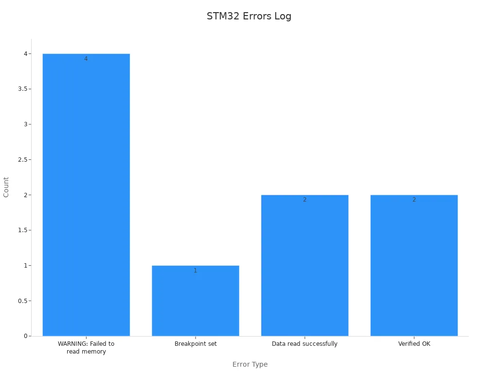
Fixing Common Problems
Firmware development can have issues like memory errors or wrong clock settings. Use error logs and debugging tools to solve these problems.
Memory Address | Status |
|---|---|
0x00036770 | WARNING: Failed to read memory |
0x000080A4 | WARNING: Failed to read memory |
0x0000C180 | WARNING: Failed to read memory |
0x0000C182 | WARNING: Failed to read memory |
0x0000C17C | Breakpoint set |
0x08001A42 | Data read successfully |
0x2004FFFC | Data read successfully |
0xE000ED14 | Verified OK |
0xE000EDFC | Verified OK |
If memory errors happen, check the memory map in STM32CubeIDE. Avoid accessing restricted areas. For clock problems, review the clock tree in STM32CubeMX. Use an oscilloscope to check signals on important pins.
Pro Tip: Update your firmware to prevent tool compatibility issues.
Testing USB, ADC, and PWM Features
Testing USB, ADC, and PWM ensures your firmware works well. For USB, use a terminal program like Tera Term to send and receive data. Check if the microcontroller responds correctly. For ADC, connect a known voltage to the input pin. Compare the digital output to the expected value. Use a multimeter to confirm the input voltage.
For PWM, connect an oscilloscope to the output pin. Look at the waveform’s frequency and duty cycle. If it’s wrong, adjust the timer settings in STM32CubeIDE.
Note: Test one feature at a time to find issues easily.
By following these steps, you can make sure your STM32F072C8T6 firmware works well in real-world projects.
Working with the STM32F072C8T6 microcontroller means setting up tools, configuring parts, and testing features. It is great for USB, ADC, and PWM tasks, making it useful for many projects. With a clock speed of up to 80 MHz and multiple communication options, it performs well and adapts easily.
Feature | What It Does |
|---|---|
Clock Speed | Runs up to 80 MHz for faster processing. |
Power Use | Works in low-power modes for battery devices. |
Communication Options | Includes 2 SPI, 2 I2C, 3 USART, USB 2.0, and CAN. |
ADC Channels | Has 16 channels for accurate analog readings. |
DAC Channels | Offers 2 channels for analog output. |
Versatile Applications | Fits industrial, medical, and home automation uses. |
You can try its advanced tools like DAC and low-power modes to build smart devices for IoT, factories, or home gadgets.
Tip: Use its GPIO pins and other features to make creative projects.
FAQ
Why is the STM32F072C8T6 good for USB, ADC, and PWM?
The STM32F072C8T6 has a 48 MHz clock and USB 2.0. It also includes a 12-bit ADC with 16 channels and advanced PWM timers. These features make it great for handling signals and communication in embedded systems.
Tip: Use STM32CubeMX to set up these features easily.
How can you debug the STM32F072C8T6?
Debugging is simple with SWD and ST-Link tools. Add breakpoints in STM32CubeIDE to pause and check your program. Use SWV to watch live data changes during debugging.
Note: Make sure SWD pins are connected correctly to the debugger.
Is the STM32F072C8T6 good for low-power projects?
Yes, it works well for low-power tasks. It has Sleep and Stop modes to save energy. These modes are perfect for devices that run on batteries.
Pro Tip: Use the HAL library to set low-power modes quickly.
What tools do you need for STM32 development?
You’ll need STM32CubeIDE for coding, STM32CubeMX for setting up peripherals, and ST-Link for programming. These tools make development faster and easier.
Tool | What It Does |
|---|---|
STM32CubeIDE | Write and debug code |
STM32CubeMX | Configure peripherals |
ST-Link | Program and debug |
How do you test USB, ADC, and PWM features?
For USB, use a terminal app to send and get data. For ADC, connect a voltage and check the output. For PWM, use an oscilloscope to see the waveform’s frequency and duty cycle.
Emoji Tip: 🛠️ Test one feature at a time to find problems easily.
See Also
Explore STM32F030R8T6 for Effective Embedded System Design
Uncover The Advantages Of STM32L151C8T6A In Sensors
Create Advanced Embedded Systems With STM32G030F6P6TR Today
Utilizing TMS320F28034 For Superior Automation System Performance

© Copyright 205 Zhongdeyuan (Hong Kong) Technology Co., Limited - All Rights Reserved.